


Stoyna Kostova
Todor Kableshkov University of Transport, Sofia, Bulgaria
https://doi.org/10.53656/isct-2025.29

Pages 335-344
Abstract. In the article general information for a brief overview of the problem status is given. Main principles of operation of caisson foundations and peculiarities in the design of deep foundations and in particular foundations with caissons are shown. Study of the stability of caisson foundations is one of the main tasks in their design. The article discusses the most significant problems related to the sizing, calculation and relevant inspections of these engineering facilities. A check of the bearing capacity of the ground, in specific engineering and geological conditions and loading from the superstructure are carried out. Technical measures in preparing the bottom of water basins for placing caissons, including materials used, specialized mechanization and process technology, ensuring the stability of the bottom of water basins are given. Special measures and regulations for the construction of the caisson, guaranteeing its stability are required. Features of transporting and laying caissons in open waters. Inspections of the deep foundations described in working and transport conditions. Computational checks and computational methods in accordance with Eurocode 7. Geotechnical. design. Part 1: Basic rules. BDS. EN 1997-1 [1, 2] are used. When solving problems related to the design of deep foundations / caissons /, the methods of Brinch – Hansen, Yanbu, Krey – Bishop etc. are presented in this article. The material is illustrated with an example and solution to a specific engineering problem. Based on the research, relevant conclusions and recommendations have been made.
Keywords: deep foundations; caisson foundations; stability check
- Introduction
Caissons are used in underwater construction. Some of them are used to providing a working space when performing deep foundations. Excavation of the soil in the area in the working chamber was carried out by workers in the past. Today, excavation work is increasingly done mainly by machines with very little human presence. When performing this type of excavation work, it is necessary to protect the workers in the chamber from prolonged stay in it. To equalize the pressure in the circulatory system of people when working at depth at a higher pressure with the atmospheric pressure that is on the surface, pressure chambers are used. The danger lies in not getting the so-called caisson disease, which is not allowed in the current state of science and technology. Another type of caisson is of the „floating“ type [3, 4, 5]. They are used for the implementation of foundation and enclosing structures performed underwater. Caissons are calculated for construction and operational conditions. It is necessary to specify the weight at which the caisson will float and the weight at which it will sink and assume its design (project) position Some of principles are shown in [6, 7, 8].
- Existing conditions
The soils on site have been investigated to a depth of 33.10m. The terrain elevation is 2.22m. At a depth of -8.58m from the terrain (10.80m) height, there is a compacted blasted rock mass with bulk density in the natural condition γn =18,5 kN/m3, φ=40°, cohesion c=0 kN/m2, unit weight underwater γ’ =11,0 kN/m3. The rock pieces are sized from 0 to 200mm. At a depth of -8.58 m from the terrain (10.80 m) there is the same compacted blasted rock mass with dimensions of 0 to 200 mm.
The layer below to an elevation of -13.48 m (with a thickness of 4.90 m) is medium-sized silty sand, with small gravel and shells with the following indicators: γn =22.1 kN/m3, angle of internal friction φ=24.4°, c=0 kN/m2, γ’ =12.1 kN/m3. Under this layer we have a clayey layer with shells, and with a thickness of (1.7 m), γn =18.5 kN/m3, φ=16.6°, c=16.4 kN/m2.
Below it to a depth of -28.58 m and a thickness of 13.40 m lies swelling clay with limestone grains with small gravel with a conditional calculated soil load qR0=300 kN/m2. Under them there is a 1.5 m thick sandy clay with interlayers of sand with shells. And coarse clay sand with shells and gravel with a thickness of 0.8 m. The last studied layer is powder clay with γn =18.1 kN/m3, φ=17.4°, c=16.9 kN/m2, E0= 261 kg/cm2. Fig. 1 shows the location of the layers and their thicknesses, and physical and mechanical characteristics.
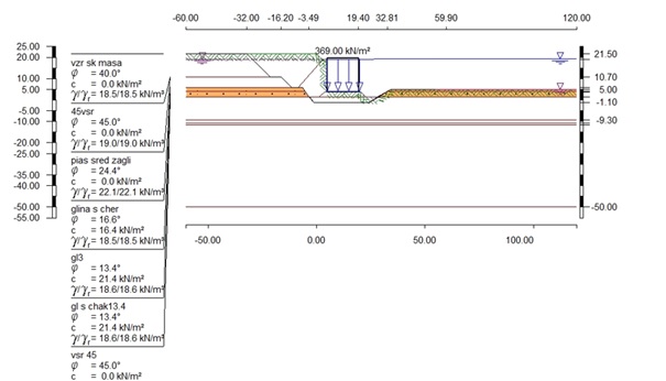
Figure 1. Location of the layers with thicknesses, physico-mechanical characteristics and load from the caisson
- Technical measures for preparing the bottom of the water basins for placing caissons
The caisson is laid on two new layers with a thickness of 2.50 m. The first lower layer is made of blasted rock mass with the following physical and mechanical characteristics: γ’ =11.0 kN/m3, φ=40°, c=0 kN/m2. This layer is laid on a previously prepared and aligned / dredged / base from the existing layer at the elevation of -19.28 m. At the depth of 21.40 m, the main layer is prepared, which is existing, swelling clay with limestone grains and with small gravel with a conditional calculated soil load qR0=300 kN/m2, unit weight in the natural condition γn =18.6 kN/m3, angle of internal friction φ=13.4°, cohesion c=21.4 kN/m2, filtration speed vs =425 m/s. The upper layer on which the caisson is placed has: γ’ =12.0 kN/m3, φ=45°, c=0 kN/m2 and a weight of the stone pieces of 5 – 100 kg.
The two sub-layers of blasted rock mass are plased successively and then are compacted. Compaction can be done with vibrating plates. After compaction the rock mass embankment should be raised in accordance with the expected settlement of the caisson. After compaction, an excavator equipped with GPS sensors can be used for more precisely align the base of the footing. Divers can also be used for alignment, and they can inspect and assess the condition of the embankment on site.
To ensure the stability of the filled material, it is good to lay the blasted rock mass in a trench dug in advance for this purpose.
- Safety checks when the caisson interacts with the earth’s foundation
The caisson subject of the article is of the floating type. The caisson used for the expansion of the port of Burgas in Bulgaria has a prismatic shape. Its dimensions are 14.50 m wide, 14.00 m high and 60 m long. The reinforced concrete bottom plate and walls are reinforced and concreted in advance under special conditions. The reinforced concrete walls are executed up to about 6.00 m high. After which the walls are completed. The caisson is filled with water during construction and during its transportation to the project site. After its installation and consolidation, it is filled with sand.
The conditions of the caisson was investigated. The water level is at an elevation of -0.28 m and the caisson is completely below this level.
The load from the caisson has been calculated. A trapezoidal load with σmax =540.0 kN/m2 and σmin =197.0 kN/m2 has been obtained. For the calculations, the load has been averaged and assumed to be uniformly distributed with a value of 369.0 kN/m2.
4.1. The check for the bearing capacity of the soil under foundation (Fig. 2)
This check was carried out according to Brinch Hansen and with Eurocode 7, Geotechnical. design. Part 1: Basic rules. EN 1997-1 [1]. It is done for 1 m in a perpendicular direction. Design value vertical loads Nd /Design value bearing capacity Resistance Rd is equal to 0.16. The check is fulfilled.
The solutions for the caisson were made with the DC Foundation computer program and its different modules DC Slope, DC Bearing, DC Settlement, DC Cantilever [9].
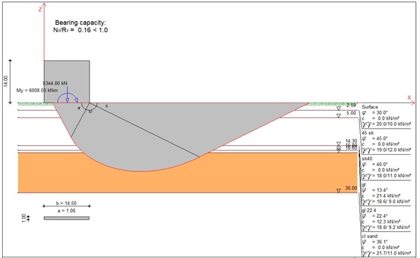
Figure 2. Bearing capacity of the soil base
4.2. Slope stability checks
First a check was made if a layer with a smaller angle of internal friction φ=40° under the caisson is placed. The stability of the caisson in this case is slightly above unity, which indicates that it is unstable. Factor of safety is 1.03 > 1.0. According to this check, it was decided that a layer with larger sizes of rock pieces and an internal friction angle of φ=45° should be placed under the caisson (Fig.3).
The caisson was checked in a state before backfilling on one side. In the operational state on the one side, the space next to the caisson is filled with blasted rock mass with the characteristics of the layer on which the caisson lays. After the calculations made according to Cray Bishop, a stable state of the caisson was obtained with a safety factor of 0.97 < 1.0.
After filling with a fraction of blasted rock mass with an angle of internal friction φ = 45° and stone fragments with a size of 5 to 100kg. The caisson has been checked for stability according to Krey – Bishop and acc.: DIN 1054:2005 EN [10]. According to this standard the Partial safety factors are given in Tabl.1.
Table 1. Partial safety factors (GEO) for LS 1C
| γ | G | Q | W | E | φ | c | cu | R,a | R,c |
| Load comb. 1 | 1.00 | 1.30 | 1.00 | 1.00 | 1.25 | 1.25 | 1.25 | 1.10 | 1.40 |
| Load comb. 2 | 1.00 | 1.20 | 1.00 | 1.00 | 1.15 | 1.15 | 1.15 | 1.10 | 1.30 |
| Load comb. 3 | 1.00 | 1.00 | 1.00 | 1.00 | 1.10 | 1.10 | 1.10 | 1.10 | 1.20 |
| Load comb. 2/3 | 1.00 | 1.10 | 1.00 | 1.00 | 1.13 | 1.13 | 1.13 | 1.10 | 1.25 |
The dates are: Raster with x from -7.90 m to 8.50 m, z from 22.60 m to 30.40
delta x = 5.00 m, delta z = 5.00 m,
with radius from R = 16.00 m to 31.00 m, delta R = 1.00 m; Load case k (Type: Lc 2)
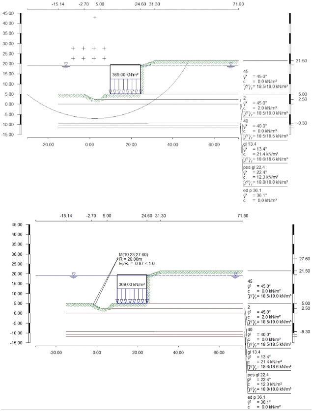
Figure 3. Slope stability check (Deep sliding check)
- slope
Fail.plane from x = -1.89 to -0.91 m
Fail.circle:x M = 10.23 m, z M = 27.60 m, R = 26.00 m
- slope
Fail.plane from x = 3.44 to 35.50 m
Fail.circle:x M = 10.23 m, z M = 27.60 m, R = 26.00 m
***** Section by a building
Loads Ed = 0.43 kN
Resistances Rd = 0.50 kN Ed/Rd = 0.87 < 1.0, see Fig. 3.
Calculation according to British Standard EN 1997-1 – Design Approach 1 Combination 1 and 2 gives the security factor of 0.91 < 1. It is being shown in Fig. 4.
For Combination 1 with partial safety factors of groups A1 “+” M1 “+” R1
For Combination 2 with partial safety factors of groups A2 “+” M2 “+” R1 are used.
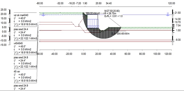
Figure 4. Slope stability check BS DA1
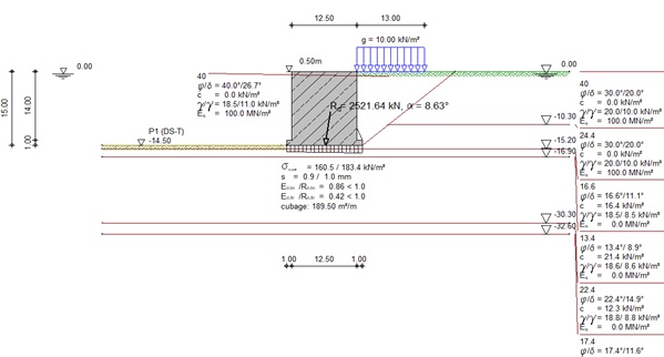
Figure 5. Check in operation conditions
4.3. Cantilever check (Fig.5)
The caisson was checked in working conditions. During its operation, the condition of the caisson approaches to the working of a supporting strengthening structure. At this stage, the caisson is placed in the project position.
It is filled with sand and its weight is determined, after that earth pressure diagrams were obtained. The decision was made according to Eurocode 7 BS 1997- 1 [11], Design Approach 1 and combination 1 and 2 and their corresponding safety factors (Table 2). The water acts on the entire height of the caisson. It is completely submerged under water.
After the calculations Static equilibrium is fulfilled, sliding resistance is fulfilled 0.47 < 1.0. Bearing capacity is ok – Nd/Rd = 0.86 < 1.0. All checks of the reinforced concrete have been completed. All verifications are fulfilled.
Table 2. Partial safety factors for section forces (STR), for safety against sliding (GEO), for bearing capacity (GEO), for slope stability (GEO)
| γ | G | E0g | W | L | E0I | Q | Qv | EP | Wg | φ | c | R,h | R,v |
| Comb. 1 | 1.35 | 1.35 | 1.35 | 1.35 | 1.35 | 1.50 | 1.50 | 1.00 | 1.00 | 1.00 | 1.00 | 1.00 | 1.00 |
| Comb. 2 | 1.00 | 1.00 | 1.00 | 1.00 | 1.00 | 1.30 | 1.30 | 1.00 | 1.00 | 1.25 | 1.25 | 1.00 | 1.00 |
Conclusion
The calculation of caissons is very responsible and complex engineering work. The specific existing conditions at the bottom of the water basin must be considered during the design. According to these conditions and the careful work of the engineers, numerous checks, acceptances and decisions are carried out, which leads to the design of a stable and long-lasting facility.
From the calculations according to different European standards, several conclusions can be drawn.
When we use European standards, multiple solutions are obtained, corresponding to the accepted combinations and different partial safety factors.
It is good for complex and responsible facilities to carry out calculations according to more than one European standard, to cover all possible combinations of coefficients and ensure the necessary stability of the facilities during their operation.
REFERENCES
[1] EUROCODE 7, Geotechnical design. Part 1: Basic rules. EN 1997-1, Bulgarian Standardization institute.
[2] EUROCODE 7: Geotechnical design Part 1: Basic rules National Annex (NA), 2015, Bulgarian Standardization institute.
[3] https://www.bricknbolt.com/blogs-and-articles/construction-guide/floating-caisson.
[4] PANTOUVAKIS, JOHN-P., PANAS, A., Computer simulation and analysis framework for floating caisson construction operations, Automation in Construction, Volume 36, December 2013, Pages 196 – 207, ISSN 0926-5805, http://dx.doi.org/10.1016/j.autcon.2013.04.003.
[5] HERRERO, E., LLATA, J., G.SARABIA, E., VELASCO, F., SAINZ, J., R.LUIS, A., RUANO, S., GUANCHE, R., Dynamic positioning of floating caissons based on the UKF filter under external perturbances induced by waves, Ocean Engineering Volume 235, 1 September 2021, 109055, ISSN 0029-8018, https://doi.org/10.1016/j.oceaneng.2021.109055.
[6] XU, C., JIANG, H., XU, M., SUN D., RUI, S., Calculation Method for Uplift Capacity of Suction Caisson in Sand Considering Different Drainage Conditions, Sustainability 2023, 15, 454, https://doi.org/10.3390/su15010454.
[7] DENG, W., CARTER, J., A Theoretical Study of the Vertical Uplift Capacity of Suction Caissons, International Journal of Offshore and Polar Engineering, Vol. 12, 2002, pp. 89 – 97, ISSN 1053-5381.
[8] DENG, W., CARTER, J., Inclined Uplift Capacity of Suction Caissons in Sand, May 2000, OTC 12196, pp. 1 – 12, doi:10.4043/12196-MS.
[9] https://www.dc-software.com/home.
[10] DIN 1054:2005 Subsoil – Verification of the safety of earthworks and foundations, by Deutsches Institut Fur Normung /German Standards/ 123 p.
[11] BRITISH STANDARD BS EN 1997-1: Geotechnical design. Part 1: Basic rules.
Dr. Stoyna Kostova, Assoc. Prof.
ORCID iD: 0009-0001-4365-0690
Department of Transport Construction and Equipment
Todor Kableshkov University of Transport
158, Geo Milev St., 1574 Sofia, Bulgaria
E-mail: skostova@vtu.bg, kostova.stoyna@gmail.com

Свързани статии:
 Leases – Business Opportunity or Source of Risk? (Analytical Approach to Financial Sustainability)
Dynamic Programming for Assessing the Effectiveness of Intelligent Transport Systems in Achieving Sustainable Development Goals
An intelligent Control Approach for Freeway Ramp Metering
Effect of Zirconium Substitution on the Microstructure and Functional Properties of Intermetallic Alloys for Hydrogen Storage
Leases – Business Opportunity or Source of Risk? (Analytical Approach to Financial Sustainability)
Dynamic Programming for Assessing the Effectiveness of Intelligent Transport Systems in Achieving Sustainable Development Goals
An intelligent Control Approach for Freeway Ramp Metering
Effect of Zirconium Substitution on the Microstructure and Functional Properties of Intermetallic Alloys for Hydrogen Storage